
PlayUAV OSD Text intensity
I'm trying to set up a PlayUAV OSD on a hexacopter but I'm having issues with white horizontal bars showing across the screen; I think it's being caused by the text intensity being too high (my previous minimOSD board worked fine in the same set-up). This only seems to happen when the video is fed through my ImmersionRC video Tx - if I connect the monitor's composite directly to the OSD then the problem disappears.
Is there any way to change the intensity of the text (as there is with the minimOSD board)?
Thanks!
/Simon
To reply to a question, please Login or registered
38 replies
Tom - PlayUAV
Favor from:
Hi Simon,
We have noticed the problem in the video Tx of recent tests. The problem seemed to be caused by the improper setting of resistance. The current R12 value is 3K and R14 value 1.5K. The value of R12 and R14 should be the same, either 3K or 1.5k. After unifying the resistance, the white bars may still appear when power on but will disappear after a while. We also find that if we increase the value of C6 and C7 from 4.7uf to 10uf, the white bar issue won't be that obvious.
We are not 100% sure about the effect of such solution yet because the white bar issue only occurs in certain video Tx. We will continue to look into the problem and find better solution. If the above method doesn't work on your OSD, please let us know.
Regards,
Tom
simoni - UAV Pilot
Favor from:
My video transmitter is an ImmersionRC 5.8Ghz 600mW, here is a link to the product:
http://www.banggood.com/Immers ... .html
I'll try the fix you suggest and see what the result is; then I'll report back. The link above is just so you know exactly what Tx is giving me the issue (in case it's useful for your testing).
/Simon
simoni - UAV Pilot
Favor from:
With both R12 and R14 at 3K the bars appear just after power-up and then disappear after a second or so leaving me with a good picture (both with and without the camera connected). I didn't modify C6 and C7 (I don't have the parts to hand) - but my issue seems to be solved :)
Changing resistors that are 0.5mm in size is quite a challenge though - even for an experienced electronics guy like myself!
Thanks for the advice though - I will modify my other board also in the same way and see if the result is consistent.
/Simon
Tom - PlayUAV
Favor from:
Great work, Simon. Truly it is tough job to change such tiny resistors. Now we can make sure it is a design fault. We will correct it in future products. Look forward to receiving more feedback from you. Thanks again for your support of PlayuavOSD.
mico
Favor from:
When I order the board now, will I receive latest one including this resistors modification?
And, one more question. What OSD chip the board use? Is the same as Minimosd use - (MAX7456)? I thought, it can only output characters, where is the trick :)?.
Thanks
~mirek
Tom - PlayUAV
Favor from:
Hi Mirek,
Yes, all the boards sold now include the resistor modification.
The OSD is drawn by STM32F405 chip. As you said, the board also uses MAX7456 chip as minimosd. But with our board, the max7456 is used to do other things like video signal gain and SYNC. If interested in this project, you can take a look at Github respository, both the source codes and hardware schematic are included.
Regards,
Tom
mico
Favor from:
Thanks Tom for the explanation. It sounds interesting and I like challenges ;). I am going to order the board.
If you can be more precise, what part of sw and hw (pins) are responsible for the OSD picture, it would be helpful.
Best,
~mirek
mico
Favor from:
I got it (hope) :). The OSD picture is on LEVEL pin. Right? And it is synced by HSYNC, VSYNC from max7456. I am going to go through the source code now. Any advice where to start is welcome.
Thanks,
~mirek
Tom - PlayUAV
Favor from:
Hi Mirek,
Yes, you are right about the OSD board. The wiki may be a good place to start with though it is still under build:-). Thank you for choosing PlayuavOSD.
Best,
Tom
mico
Favor from:
Hi,
I just received my board and did first tests. Unfortunately, I have the same problem as in this topic - horizontal bars when connected to ImmersionRC VTX (250mW, 5.8GHz), not appeared on directly connected display. I was assured that the modification of resistors is already done on board I have ordered. I am not sure if it is true, I am not able to measure them. The board version is 2015-03-06-VER1.2. Should I find somebody to modify my board (resistors) or the modification is already done and issue is something else?
Thanks,
~mirek
mico
Favor from:
Hi,
both resistors have the same value - 3k, so modification was done. Unfortunately issue persists. Any idea?
Thanks
~mirek
Tom - PlayUAV
Favor from:
Hi Mirek,
The board was printed in March, while the components were mounted recently. Would you like to show some pictures or video?
regards,
Tom
mico
Favor from:
Hi Tom,
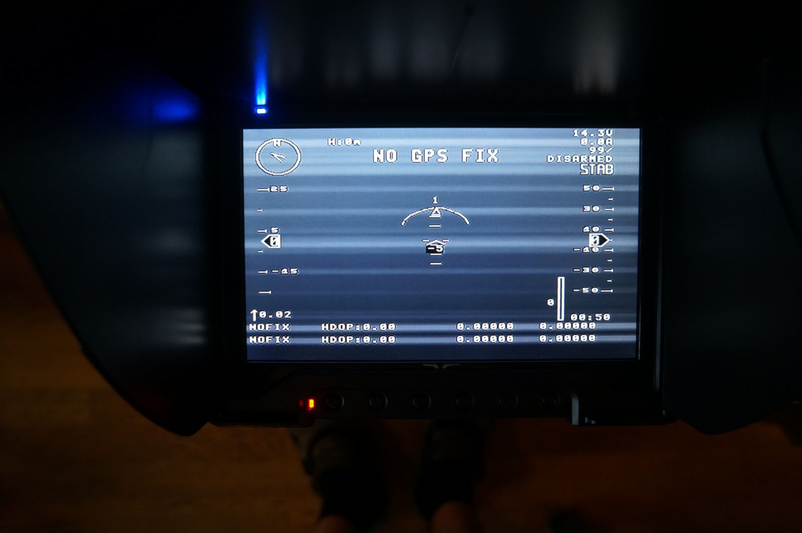
here is the screenshot from the video recorded by fatshark googles.
Best,
~mirek
Tom - PlayUAV
Favor from:
Hi Mirek,
Thanks for the reporting. I don't have an ImmersionRC VTX (250mW, 5.8GHz). Could you please do some testing to find if it is caused by video input or output?
Input testing:
Please try to test without a camera input. Or change to another camera.
Output testing:
Please try to connect the OSD's video out to the screen directly(no VTX).
It may be caused by the signal scope of video output by OSD which does not fit well with your VTX. On the OSD board, the chip MAX7452 does the video signal gain. Currently, we connect both the AGCD and GSET to +5V, then MAX7452 will output the signal Vout=2Vin, as shown below:
If you have soldering experience, please connect the AGCD to GND instead of +5V. Then the MAX7452 will output the video signal with 2Vp-p fixed. See below:
Regards,
Tom
mico
Favor from:
Hi Tom,
Camera source change has no influence, the output is the same.
OSD output connected directly to my goggles (no VTX) is OK.
Unfortunately, I am not able do the test with AGCD at the moment.
Regards
~mirek
Tom - PlayUAV
Favor from:
Hi Mirek,
Could you please show me a picture of your VTX? The purchase link will also be helpful. I should buy a same or similar for testing. Thank you.
Regards,
Tom
mico
Favor from:
Hi Tom,
it is FatShark - 250mW 5.8GHz A/V Transmitter
for example:
http://www.readymaderc.com/sto ... 3D485
best,
~mirek
Tom - PlayUAV
Favor from:
Hi Mirek,
Thanks for the info. I found a similar item on TaoBao
What Receiver are you using?
Regards,
Tom
andy
Favor from:
Hi Guys,
I have heard that latest IRC VTx's use a larger signal amplititude than standard AV video. (We figured this may be to try to increase the range) I dont know if that might be the cause of the issue?
You could try checking the value of resistance between the Video transmitter input from camera, and ground. It appears that they achieved the increased amplitude in the Vtx by increasing the resistance from signal to ground from 75 ohms to 110 ohms or something similar
regards
Andy
mico
Favor from:
Hi Andy,
you're right, I measured 110 Ohm on input of my VTX. What does it mean? Do we have low signal from OSD to feed this VTX? Should the AGCD to ground proposed by Tom help? Or should I put some parallel resistor on VTX input to get 75 Ohm?
@Tom, I use http://www.readymaderc.com/sto ... 3D524 in my Fatshark Dominator Goggles, but I don't think it has influence. Btw. the same setup with MinimOSD works great. I measured output resistance on PlayuavOSD - 75 Ohm, the same on MinimOSD - hi resistance > 1MOhm.. ???
Thanks and best regards,
~mirek
Tom - PlayUAV
Favor from:
Hi Mirek,
I have looked at the "ImmersionRC 600mW 5.8GHz audio/video transmitter Instruction manual". It requires 1Vpp as video input.
It does not mention such information in the manual of 250mW VTX. But we can be sure that it has a design fault in PlayUAV OSD board. With the MAX7452's output, we should output fixed 1Vpp or 2Vpp.(Current is 2VIN, it works with all VTXs we have and other common VTX).
For your VTX, I guess it increases the video range itself like Andy said. So I suggest that you try configing MAX7452's Gain Control to output 1Vpp or 2Vpp. Please see the config table below:
If it works, we will modify the board in the next version to make output configurable(1Vpp or 2Vpp).
Attached is the manual of ImmersionRC VTX 250mW and 600mW.
Regards,
Tom
Tom - PlayUAV
Favor from:
Another word, you need not do the above test case. There should be no improvement. Actually, we find that the issue may be caused by the voltage amplitude being too high when we overlay the font. If you switch to a panel with little or no output, you would get a clean picture. Anyway we are doing the testing, I will keep you updated.
Regards,
Tom
mico
Favor from:
Hi Tom,
Thanks for the update. One more thought: are you sure the R13 is there correctly? I think, output impedance should be high... As I will have time, I do remove the R13 and will see.
BR
~mirek
mico
Favor from:
Hi Tom,
I removed the R13 and the result is the same. Actually no change, no better, no worse... :). Absolutely the same setup, but with the minimOSD works well. Is the intensity of the overlay graphics/font possible to control by the firmware or it is done by the hardware? The minimOSD board has a possibility to set the font intensity by the setting, but I didn't test if there is any difference...
BR
~mirek
Tom - PlayUAV
Favor from:
Hi Mirek,
Sorry for the late reply. We have done some tests and found that the problem might be with MAX7456. With OSC, we find chip MAX7456 outputs the video with 2Vp-p, which means that the black-level becomes lower. When we put text onto the screen, the pixel supposed to be black is taken as white, so the white line only appears when we output text (you could switch to an empty panel and there should be no white line).
If we remove R6(MAX7456 pin 26) and connect the video-in and ADG733 with a series capacitor(10uf) together, meaning we put the text with the 1Vp-p video reference, the white line disappears(only one of our VTXs seems to have this issue with slight white line, so the improvement is not obvious).
Current progress:
1) We have ordered some VTXes including your FatShark 250mW for more testing(they are on the way).
2) The series capacitor mentioned above is just for testing. We will test with a MAX7452 add between MAX7456 and ADG733.
3) We are making a new board for testing. If this issue can be solved, we will produce the new board. I will send a new board to you, since it is hard to modify the current board for your VTX.
Regards,
Tom
mico
Favor from:
Thanks a lot Tom,
OK, I'll wait for your conclusions and possibly I will await a new board.
BR
~mirek
mico
Favor from:
Hi Tom,
do you have any progress and/or conclusions?
BR
~mirek
Tom - PlayUAV
Favor from:
Hi Mirek,
We are working on this, but it seems hard to get a perfect solution. Anyway, I will post here if there is progress.
regards,
Tom
BuBu
Favor from:
Hi,
I just found this discussion completely randomly. I had exactly the same issue with a DragonOSD+ v2 and the same video Tx (tried the immersionRC 600 mW and the Fatshark 250 mW), and as you suspect it seems to be a black or white level issue.
However, as far as I understood, it seemed to be actually due to the camera, more than to the video Tx. I use a Fatshark 650 TVL and apparently other cameras are less prone to give this issue.
This was just wrote in case it could be useful.
Tom - PlayUAV
Favor from:
Thanks for you information. From our testing, the reason is that the OSD board not handle the video signal perfectly. I don't have a DragonOSD, but for PlayuavOSD it caused by putting text based on non-standard video signal. We should make the video signal to 1Vp-p fixed before processing OSD, and make the OSD video output can be configurable(output 1Vp-p, 2Vp-p and etc).
PlayBoy
Favor from:
Hi Guys,
I also have the same problem- horizontal bars but I think I have the new version, but I´m not really sure.
I have the 2015-03-05-VER1.2 andmy resistors R12 is 3K even the R14 is 3K too!
So I think I have the new or lets say "other" version than the PCB with 1,5K and 3K resistor!?
....But in the end, I have the same problem, any Idea?
Did I have the actual Version or not? What can I do reduce the horizontal bars?
... by the way I have a Fatshark TX too.
Cheers
Tom - PlayUAV
Favor from:
Change the resistors can improve the image quality, but not a perfect solution. Currently, we are making some sample boards, if no problem found, the production will follow.
Regards,
Tom
PlayBoy
Favor from:
Hi Tom,
But For Both R12 and R14 I still have 3K right now!?
So I'm wondering wich Parts I have to change for optimizing?
Do You see any Solution for filtering with ferritts or caps outside, maybe power inputs too?
Also some if my Information lines are flickring, sometime more sometime netter.
Bes Regards
Kozy2009
Favor from:
Hi, Tom.
I think I have similar issue of white lines.
I use Boscam/SkyZone 600mW (TS832).
http://www.hobbyking.com/hobby ... .html
wsalopek
Favor from:
Hi folks,
I have a version of this same problem...my video monitor looks fine, but I get large white lines in my Fatshark Dominator V3 goggles all across the screen horizontally where text is being displayed.
I had tried a possible solution involving a capacitor, which someone else described as successful, but it did not work for me, post #9:
http://fpvlab.com/forums/showt ... m-OSD
So...
Has there been any progress on this issue? I really don't wanna go back to minimosd.
Thanks...
--
- Bill-
-
gnrc
Favor from:
Try adding a ~50 Ohm resistor between video and gnd between cam and osd, that should fix it.
The white lines are mostly issues with too high video levels which the resistor solves.
If you still have issues but it is better try 75 or 100ohms
wsalopek
Favor from:
gnrc,
Thanks for that. Will this work?
http://smile.amazon.com/uxcell ... istor
So you are saying I need 2? One each, in-line, on the ground wire and video wire? Sorry I am not that familiar with electronic components.
Thanks...
Bill
gnrc
Favor from:
Those are way more powerful then they need to be
You can find ones similar to those:
http://www.ebay.com/itm/47ohm- ... Wbqfn
http://www.ebay.com/itm/75ohm- ... Wbqfn
http://www.ebay.com/itm/100PCS ... WZnGU
on amazon/ebay but from the us to similar prices.
And you need one. One end goes to the signal wire, the other to the ground wire. Be sure to insulate that the wires do not touch directly.
I would just get a couple sizes (e.g. 47, 75, 100ohm) to try which works best for you.
1/4w is plenty for the use and it does not matter if they are 1% or 5% and either metal or carbon film ones work